Aquiring data about the I2S capabilities of currently available mini computers proofs to be quite difficult. While there is some information about the I2S capabilities of the RPi, there seems to be nearly to none about the Odroid C1+ mini computer which was released in Summer 2015. However, in order to decide which platform is more suitable for audio projects, it is important to have some insights about jitter, data format etc. This article tries to gather information from various sources, sum it up and do some measurements and try to compare the two platforms..
Raspberry Pi
For the Raspberry Pi there is already some information about the I2S bus available, whereas the best seems to be on this page:
https://hifiduino.wordpress.com/2014/11/13/raspberry-pi-b-digital-audio/
To sum it up, the I2S interface of the RPi has the following limitations:
- The RPi does not have any clock that is accurate for the needed I2S clocks, so it generates it out of the internal clock.
- It has only a bit depth of 16 bit, no Hi-Res audio (24bit) can generated
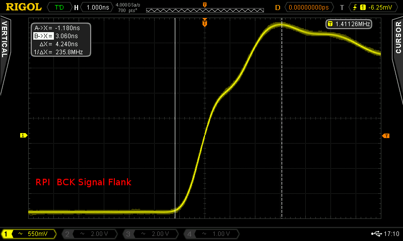
Measuring the I2S clock signal (BCK) one can easily see how the clocks are generated which leads to jitter:

One can see that the signal alternates to create the needed clock speed which unfortunately leads to a fixed jitter of 2.5ns.
A look at the signal rise time could be interesting too – 4.2ns look nice to me:
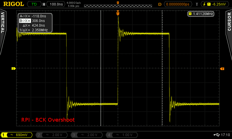
The I2S signals of the RPi have quite some overshoot as can be seen here, however, I’m unsure if this could have any interesting impact:
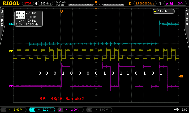
Let’s now have a look at two I2S signals – one with 48/16, the other with 48/24:
Sine Mono, 1Khz, 48kHz / 16bit
Sample 2: 4652 | 0001 0010 0010 1100
Sine Mono, 1Khz, 48kHz / 24bit
Sample 2: 1094933 | 0001 0000 1011 0101 0001 0101
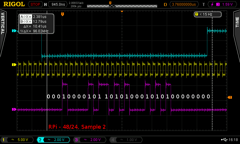
The signal is bit correct as it should be. However, it is very interesting that the Raspberry Pi can obviously generate 24bit signals as the diagram above clearly shows. The driver switches from 16 to 32 bit and sets the last 8 least significant bits to “0”. Probably the truncation from 24 to 16 bit (as mentioned in other articles) has been a driver issue and is not due to hardware limitations.
Odroid C1+
For the Odroid C1+ unfortunately there is nearly no info about the I2S signals at all, for instance, it is unknown how the I2S clocks are generated. Measurements of the signal led to the following results:
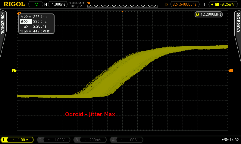
One can see that the jitter is present here, too, with about 2.2ns max. However, when looking closer, one can see that most of the clock signals are within certain limits as can be seen in the following picture:

So, about 99% jitter is approx 1ns, which seems to be better than the jitter in the Raspberry Pi.
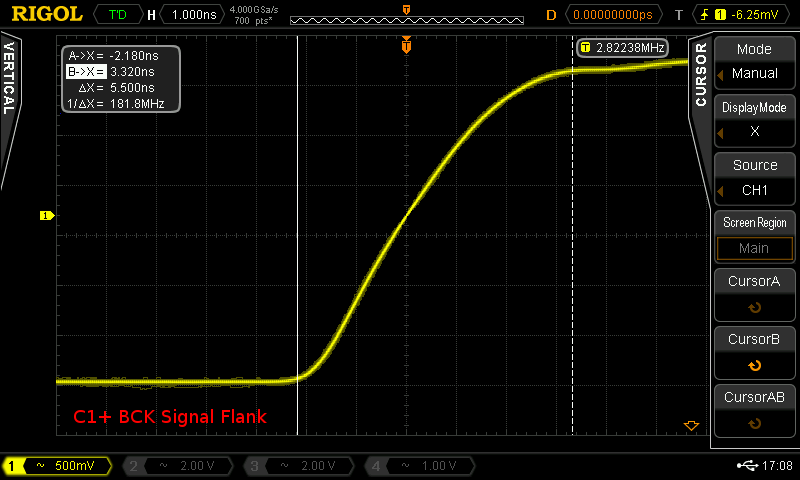
The signal rise time is similar to the RPi, a bit higher with around 5.5ns:
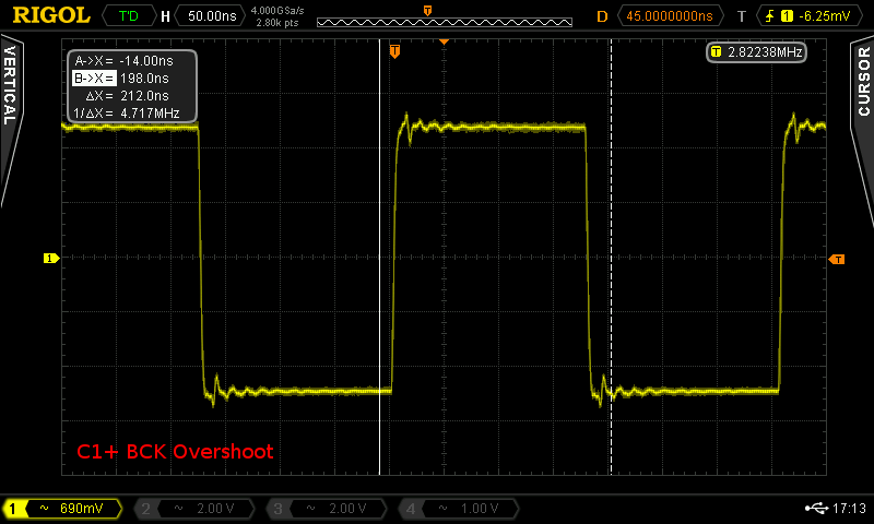
The overshoot of the C1+ is lower:
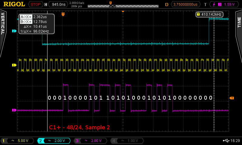
The I2S data signals on the Odroid C1+ look as follows
Sine Mono, 1Khz, 48kHz / 16bit
Sample 2: 4652 | 0001 0010 0010 1100
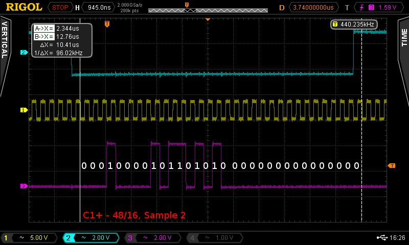
The signal is bit correct, too. In comparison to the Raspberry Pi, the signal seems to be always 32bit long, whereas the 16 LSB bits are set to “0”. However, this could also be some driver issue.
Sine Mono, 1Khz, 48kHz / 24bit
Sample 2: 1094933 | 0001 0000 1011 0101 0001 0101
As expected, the signal is bit correct too, so it seems, the Odroid C1+ works the same as the Raspberry Pi.
A brief look at the noise could be interesting, too:
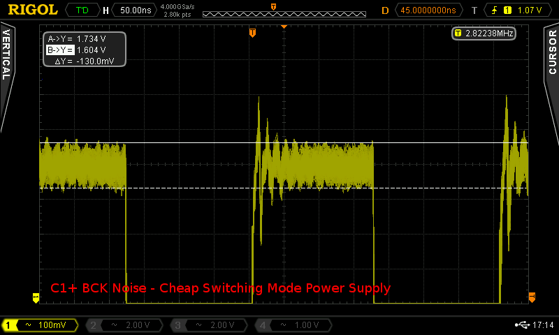
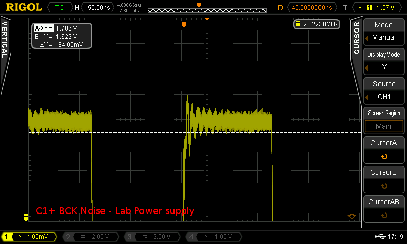
For the measurement above, a cheap switching mode power supply was used. When powering the C1+ with a lab power supply, the noise is reduced:
Comparison / Conclusion
The Raspberry Pi and the Odroid C1+ perform quite the same regarding the I2S signal, I would say. The primary differences and advantages/disadvantages of the platforms could be summed up as follows:
- Performance/Power: The Odroid C1+ feels a lot faster and responsive than the RPi. It does, however, consume twice as much power as the RPi. It probably depends on the application, which platform is more appropriate.
- Jitter: For jitter, both platforms perform similar. The jitter is approx. 2.5ns for both platforms, whereas the RPi distributes the jitter quite precisely to two frequencies, while the C1+ spreads jitter evenly but on the other hand statistically most jitter is less than 1ns. I cannot tell if there are be any audible differences, but I would estimate that the Odroid C1+ performs better as overall jitter seems lower. Anyway, due to the missing oscillators which can generate exact I2S BCK signals, both platforms (and probably most similar mini computers) suffer from this issue. The only solution would be reclocking, whereas I know of two projects in this area: The Acko S03, which is simple and cheap but cannot eliminate jitter completely due to its design and Ians Reclocker, which is based on a buffer and should create very exact signals but seems to be more expensive and not so easy to obtain.
- Signal Encoding / Bit correctness: Both platforms seem to encode the I2S signal correctly. The only difference seems to be that the RPi encodes 16 bit signals in 16bit packages, while the C1+ always uses 32-bit packages. I cannot say how DACs would handle this, however, I estimate that most should be compatible to both encoding schemes.
- Noise: Although this may not have too much impact, and most users will anyways use some kind of isolator ICs to isolate the I2S signal, a decent power supply for the RPi / C1+ is always a good option.
Well, maybe the above findings clear things up a little and give some insight, however, it would be a major advantage if the clock generation circuits of the discussed hardware would be released openly.